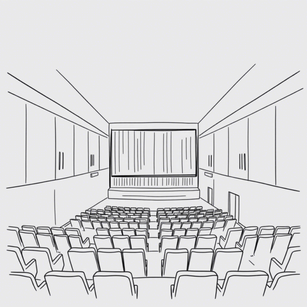
Before initiating any seat installation project, a comprehensive physical site survey is essential to ensure alignment with design specifications, structural constraints, and operational requirements. This process involves systematically evaluating the installation environment to identify potential risks, verify spatial compatibility, and confirm readiness for implementation.
The following 20-point checklist has been developed to guide technicians, project managers, and site inspectors through the critical aspects of a physical survey. It covers spatial measurements, anchoring conditions, accessibility, safety compliance, and integration with existing infrastructure. By adhering to this checklist, teams can minimize installation errors, streamline execution timelines, and uphold quality standards throughout the deployment phase.
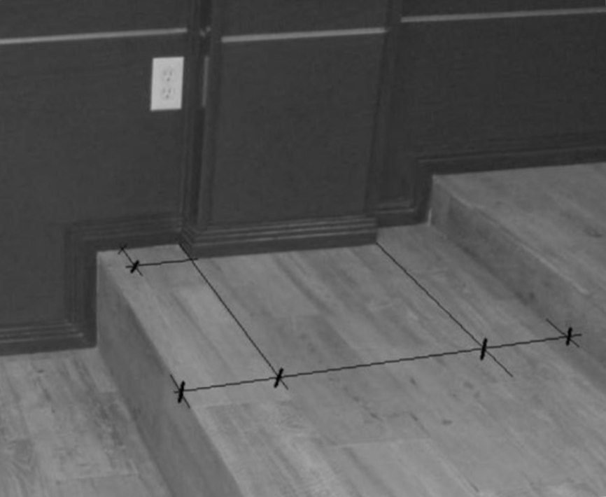
Measure and register the following:
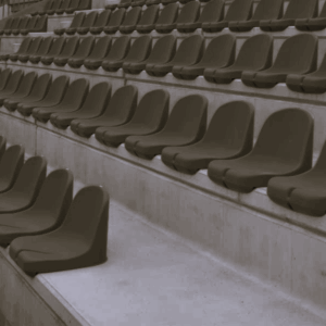
1. Available space for chairs.
All measurements should be taken directly on the floor surface whenever possible. It is essential that these measurements are referenced between fixed physical boundaries that define the usable space. These boundaries may include—but are not limited to—carpet edges, lighting strips, steps, walls, parapets, or any architectural features that physically constrain the area. This approach ensures dimensional accuracy and alignment with real-world conditions, minimizing discrepancies during layout planning and installation.
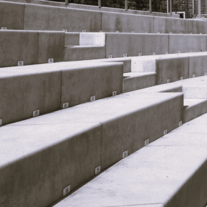
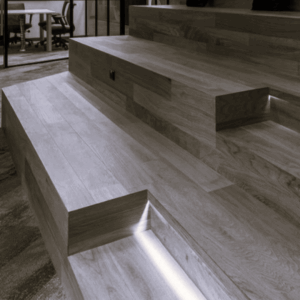
2. Treads’ width.
It is essential to document any protruding elements—such as nosings or other features—that reduce the usable tread width. If such elements are present, their dimensions must be measured and subtracted from the total tread width to determine the effective walking surface.
In addition to measuring each individual tread, special attention should be given to the final (top) tread. This tread often differs in width and is typically wider than the others. Its exact dimensions must be recorded separately to ensure there is same usable as lower in treads.


3. Risers’ height.
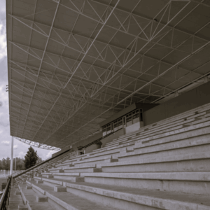
It is essential to document the geometry of the steps and platforms that form the seating tiers. Key aspects to record include:
- Step Height (Riser Measurement): Measure the vertical distance between each seating tier. This riser height affects visibility, accessibility, and compliance with safety regulations. Consistency across tiers is crucial for ergonomic flow and audience comfort.
- Floor Inclination Check: Verify whether the horizontal surface of each tier (where seats are mounted or where people walk) has any slope or inclination. This is particularly important in stadiums or auditoriums where drainage, sightlines, or accessibility may be affected.
- Cross-Sectional Profile Documentation: Capture the shape and structural profile of each tier, including tread depth, edge treatments, and any overhangs or recesses. A clear diagram or annotated photo of the cross-section helps ensure accurate replication in technical drawings and supports decisions related to seating layout, lighting, and safety features.
These measurements are foundational for architectural planning, retrofitting, or compliance assessments, and should be recorded with precision and contextual notes where applicable.

4. Slope Measurement for Inclined Flooring.
To determine the slope of a ramped floor surface, a basic manual method involves the use of a leveling tool positioned horizontally. The total length of the level (denoted as L) is recorded, and the vertical distance (H) from one end of the level to the floor surface is measured. This height differential provides the basis for calculating the floor’s inclination using trigonometric or ratio-based methods.

H = height (measured vertically)
R = ramp floor
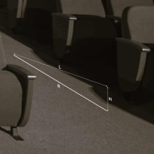
In addition to manual techniques, electronic slope meters or digital inclinometers may be used to directly obtain the angle or percentage of inclination. These devices offer increased precision and efficiency, particularly in environments where rapid or repeated measurements are required.
Both methods should be documented clearly, noting the measurement points and any relevant environmental conditions that may affect accuracy.
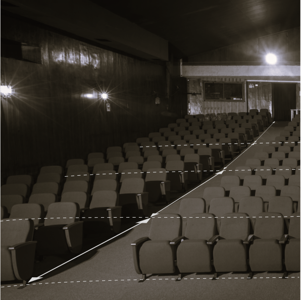
5. Ramp Profiling for Seating Pedestal Specification.
Location within the room of the break lines where the floor changes inclination.
For a theater or cinema hall featuring sloped flooring, each ramp segment must be individually documented. The following parameters are to be recorded for every ramp:
- Ramp Length: Measure the horizontal length of each inclined section.
- Inclination Angle or Slope: Determine the angle of inclination or slope percentage using appropriate tools (e.g., digital inclinometer or laser level).
- Positional Reference: Note the ramp’s location within the overall layout of the hall, referencing fixed architectural features or grid coordinates.
This data is essential for determining the required pedestal specification for each seat installed on a sloped surface. Accurate ramp profiling ensures ergonomic seating alignment, visual line-of-sight optimization, and compliance with design specifications
6. Chord and arrow of base for arc rows.
1. Definitions
- Chord (C): Straight-line distance between the arc’s endpoints
- Sagitta (F): Perpendicular height from the midpoint of the chord to the arc’s apex
- Radius (R): Estimated radius of curvature, assuming a circular arc segment
2. Measurement Procedure
2.1 Identify Arc Endpoints
- Locate and mark the two endpoints of the arc on the floor.
- Measure the straight-line distance between these points using the tape.
2.2 Determine Midpoint and Sagitta
- Calculate the midpoint of the chord by dividing the chord length by two.
- From this midpoint, measure perpendicularly to the highest point of the arc.
- Record this vertical distance as the Sagitta (F).
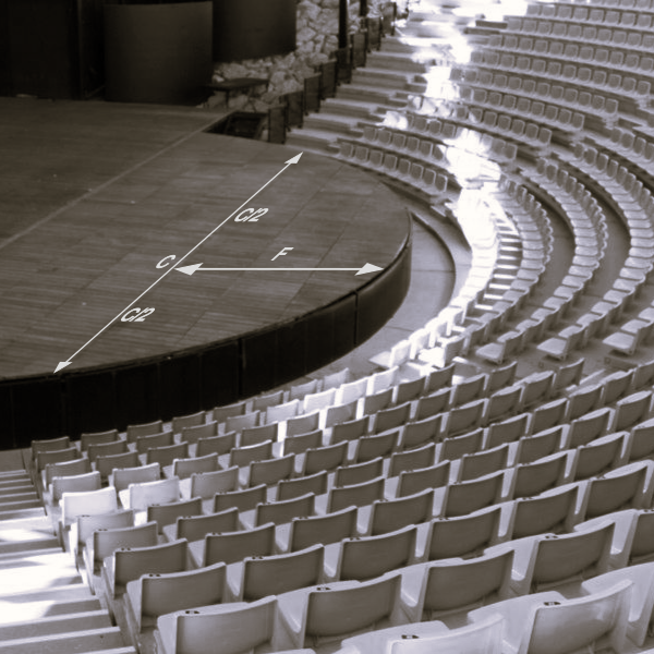
3. Radius Estimation
- If the arc is assumed to be part of a circle, estimate the radius using the following formula:
R = (C × C) / (8 × F) + (F / 2). - The arc can be estimated also by drawing a circle using the noted data.
7. Row Spacing Considerations in Curved Grandstand.
Accurate measurement of row spacing is essential to ensure compliance with safety regulations and user comfort standards. It also plays a critical role in determining the appropriate seating type for each installation.
In the construction of curved grandstands, it is common for builders to deviate from concentric layouts due to structural or design constraints. This non-concentric configuration often results in variable row spacing—typically narrower at the lateral edges and wider toward the center. Such variation can impact both accessibility and seating ergonomics.
Therefore, during the physical site survey, it is necessary to verify the tread width at multiple points along each row, specifically at the center and at both ends. This ensures that any dimensional discrepancies are identified and accounted for in seating selection and layout planning.
8. Survey of obstructive elements relative to seating layout.
Identify and document all elements that may interfere with the installation of seating, whether located on the floor—such as electrical boxes, air vents, or lighting strips—or on the walls, including protruding columns, speakers, audio outlets, data ports, and similar components.
Each element must be located and referenced with respect to key architectural features, including riser elevations, wall surfaces, and seating row boundaries, to ensure accurate spatial coordination and avoid conflicts during installation.
9. Measuring a Polygonal or Irregular Floor Plan.
This procedure details a systematic approach for capturing the precise geometry of a commercial space with a polygonal or complex non-rectangular envelope, which may consist of four or more sides and include re-entrant angles. The objective is to create a scaled plan by collecting a comprehensive set of linear measurements through triangulation, suitable for CAD reconstruction. The method leverages the distanciometer for long and diagonal measurements and the tape for baseline and perimeter verification.
1. Preparation and Equipment
- Instruments: Distanciometer (Laser Distance Meter), Retractable Tape Measure (e.g., 8m / 25ft), Clipboard, Graph Paper, Pencil.
- Principle: The polygonal space will be subdivided into a network of triangles from a stable baseline. Measuring all three sides of each triangle (triangulation) allows for precise reconstruction without angular instruments. A fundamental requirement for all distanciometer measurements is that the device must be held perfectly horizontal when measuring between vertical surfaces. Failure to do so will result in inaccurate, longer-than-actual horizontal distances due to Pythagorean error.
2. Establishing a Control Baseline
- Sketch: Create a rough field diagram of the space, numbering each vertex of the perimeter sequentially (e.g., A, B, C, D, E, F…).
- Select Baseline: Identify the longest, most accessible wall to serve as the primary baseline (e.g., Wall A-B). This line is the foundation for the triangulation network.
- Measure Baseline: Using the tape measure, physically measure and record the length of the baseline (A-B). This provides a high-accuracy reference to calibrate against and mitigate error accumulation.
3. Primary Triangulation from the Baseline
This step captures the spatial relationship of all vertices relative to the established baseline.
- From point A, use the distanciometer, ensuring it is level, to measure the diagonal distances to every non-adjacent vertex (e.g., A-C, A-D, A-E, A-F, etc.). Record these.
- Move to point B. Again, using the leveled distanciometer, measure the diagonals from B to the same set of vertices (e.g., B-C, B-D, B-E, B-F, etc.).
- You have now created a series of triangles sharing the common baseline A-B (e.g., Triangle A-B-C, A-B-D, A-B-E, etc.). For Triangle A-B-C, for instance, you know:
- A-B (taped baseline)
- A-C (distanciometer diagonal)
- B-C (distanciometer diagonal)
4. Capturing the Complex Perimeter and Internal Features
- Perimeter Segments: Measure and record every segment of the multi-sided outer perimeter with the tape measure (e.g., B-C, C-D, D-E, E-F, F-A). These are critical for verifying the triangulated data and defining the exact wall lengths.
- Complex Wall Profiles: For curved walls, alcoves, or jogs, establish secondary baselines.
- For instance, across a recessed alcove between points C and E, measure the chord C-E as a new baseline.
- From the endpoints C and E, use the leveled distanciometer to measure to the deepest point of the alcove, creating a new triangle to define its geometry.
- Measure the perimeter segments of the alcove with the tape.
- Vertical Elements: Use the distanciometer to measure ceiling heights. Use the tape to measure sill heights, column dimensions, and the precise location of obstructions from the nearest walls, taking care to keep the tape horizontal for any non-vertical measurements.
5. Verification and Closure for a Multi-Sided Envelope
- Discrepancy Check: Systematically compare the taped perimeter measurements (e.g., C-D, D-E) with the corresponding sides derived from the triangulation network. Minor discrepancies are expected; prioritize the taped measurement for actual wall lengths.
- Diagonal Closure Check: In a polygonal shape with multiple vertices, take additional “check” diagonals with the leveled distanciometer between points not directly connected in the initial triangulation (e.g., from D to F). When the plan is drawn in CAD, this measured distance must match the drawn distance, validating the accuracy and closure of the entire survey.
Key Technical Considerations
- Horizontal Integrity: The most common source of significant error in this method is failing to keep the distanciometer horizontal. Always double-check the device’s orientation, using its bubble level if available. For critical long diagonals, taking multiple measurements from slightly different positions can confirm consistency.
- Error Control: The web of triangles and the multiple verification steps (taped perimeter vs. triangulated edges, closure diagonals) create a robust system for identifying and isolating measurement errors inherent in complex, multi-sided spaces.
This collected dataset provides all necessary information to accurately reconstruct the irregular, polygonal floor plan in a vector drawing program with a high degree of confidence.
10. Floor finish and substrate identification.
When conducting a physical survey for seating installation, it is essential to document both the floor finish and the underlying substrate material. These details directly impact anchoring methods, drilling requirements, and long-term stability of the seating system.
🔍 Why It Matters
- Anchoring Compatibility: Different finishes and substrates require specific fasteners or adhesives.
- Load Distribution: Substrate strength affects how weight and vibration are absorbed.
- Installation Planning: Knowing the floor composition helps anticipate tools, labor, and potential surface preparation.
📋 What to Record
For each seating area, note:
- Type of floor finish (visible surface layer)
- Material of the subfloor (structural base beneath the finish)
- Thickness of each layer, if available
- Any slope or irregularity in the surface
🧱 Common Floor Finishes
- Ceramic tile
- Porcelain tile
- Polished concrete
- Epoxy coating
- Vinyl flooring (VCT or sheet)
- Carpet (low-pile or commercial grade)
- Wood (engineered or hardwood)
- Rubber flooring
🧱 Common Subfloor Materials
Raised access flooring (metal or composite panels).
Reinforced concrete slab
Steel deck with concrete topping
Wood (plywood or OSB) over joists
Lightweight concrete
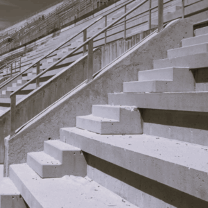
11. Measure and record aisles and steps width.
12. Room total width.
13. Room total length.
14. Screen height.
15. Stage height.
16. Floor to ceiling height.
17 . Length and height of secondary walls.

18. Carpet boundary’s longitudinal location.
Longitudinal location within the room of carpet boundaries (front, middle and back).
19. Keep measurement tape or lasser beam horizontal.
Keep the tape or laser beam horizontal for all length and width measurements.
20. On ramp register ramp slope.
For measurements done on a ramp we have to register the ramp slope. Or register the elevation difference between point to point of the taken dimension.